KOBOLD Instruments Inc • 1801 Parkway View Drive • 15205 Pittsburgh, PA • Tel: +1 412 788 2830 • E-mail: Please activate JavaScript • visit koboldusa.com
 Magnetic
Frequently Asked Questions (FAQs): Magnetic inductive flow meter
How does a magnetic inductive flow meter work?
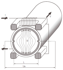
A magnetic inductive flow meter (abbreviated to MID or Magmeter) works according to Faraday's law of induction.
As a result, a voltage is induced in a conductor moving in a magnetic field. The electrically conductive measuring medium corresponds to the moving conductor in the process. The voltage induced by the measuring medium is proportional to the flow rate and is therefore a measure of the volume throughput. Flow measurement requires a minimum electrical conductivity of the flowing medium. The induced voltage is fed to a measuring amplifier via two electrodes that are in conductive contact with the medium. The volume flow is calculated using a defined pipe diameter. This measurement is independent of the medium and its material properties such as density, viscosity and temperature.
What Are The Advantages of Magnetic Inductive Flow Meters?
From a technical point of view, there are almost no limitations:
• There are no moving parts, so wear and tear and mechanical failure are excluded
• This results in reduced maintenance costs and a long service life
• The use with clean, hygienic, dirty, corrosive or abrasive media is possible, these media have no negative influence on the measurement
• Easy and space-saving installation in confined spaces
• Requires little power to operate
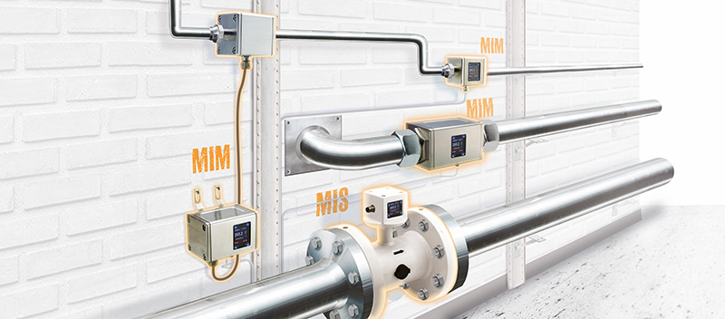
• Capable of measuring both low and high flow rates; the MIM from Kobold can measure 0.01...1 liters per minute with the G 1/4 inch connection, with the two inch connection the MIM has a measuring range of 3...650 liters per minute. MIS, EPS and PIT series are available for even larger nominal diameters
• Bidirectional measurement is possible
• Insensitive to fluctuations in viscosity, density, temperature or pressure
• Very precise with at the same time only a low pressure drop and only a short inlet and outlet section
What are the Disadvantages of Electromagnetic Flow Meters?
• They can only be used with conductive liquids, minimum conductivity > 5-20 micro-Siemens/cm. Electromagnetic flow meters rely on the electrical conductivity of the fluid to generate a measurable signal. Since conductivity is temperature-dependent and influenced by the chemical composition of the medium, it can vary during operation. If the conductivity drops below the minimum required level, measurement accuracy may be affected or the device may cease to function.
• It must not contain any dissolved carbon hydrides such as petrol or diesel
• Fluids must not contain any magnetic materials
• Completely filled tube is required (no gases, no air bubbles)
How Accurate Are Magnetic Flow Meters?
Compared to other flow measurement methods, magnetic inductive flow meters always deliver higher accuracy. The exception to this are the Coriolis flow meters. However, Coriolis meters are very expensive to buy. For example, the Kobold EPS has an overall accuracy of around 0.3% at a flow rate of 10 m/s.
Ultimately, the user has to weigh up the costs, benefits, needs and technical feasibility.
What is the difference between a flow meter and a flow switch?
A flow meter shows the current or accumulated flow. A flow switch issues an alarm if predefined values are exceeded or not reached.
What is the turndown ratio for a magnetic flow meter?
There is often a clear difference in the measuring range ratios between measuring devices. Be it that it is a matter of different sizes or other technologies. If turndown is an important factor in your application, you need to ensure that the gauge you choose meets those requirements.
For example, the measuring range ratio for variable area flow meters can be 1:10. However, there are other measuring principles with larger measuring range ratios.
Electromagnetic flowmeters generally provide a turndown of 1:250 or greater. This is higher than many other measurement principles.
What applications are there for electromagnetic flowmeters?
Electromagnetic flowmeters are used in a wide variety of applications. Common examples include water management, process water, wastewater (treated and untreated), food processing, chemical and corrosive materials, sludge and other general industrial applications.
What are the Differences Between Magnetic Inductive Flow Meters and Coriolis Flow Meters?
Coriolis meters offer true mass measurements, while magnetic inductive flow meters only provide volumetric flow measurements. Your application may be affected by certain parameters for which a mass flow measurement would be more appropriate. Coriolis meters also generally offer a higher turndown ratio than magnetic flowmeters for applications where the flow is not uniform in velocity.
The biggest difference when choosing between a Coriolis mass flow meter and a magnetic flow meter is the cost. Coriolis mass flow meters are typically significantly more expensive than the average magnetic flow meter. Unless there is a compelling reason in your application that a magnetic flow meter cannot meet, a magnetic flow meter is often a better choice.
One reason that might indicate the need for a Coriolis mass meter would be that the medium is not conductive or not conductive enough for a magnetic flow meter and the customer wants to measure their flow in units of mass. Electromagnetic flowmeters also require a stable flow profile. This presupposes certain requirements for the pipelines before and after the measuring device (inlet/outlet section) as well as the consideration of any flow disruptors such as valves, bends and pumps.
These requirements do not apply to Coriolis meters. So if the installation location does not allow for the inlet and outlet sections required for the proper functioning of an electromagnetic flow meter and mass is also to be measured, a Coriolis mass meter can easily solve these problems.
Coriolis mass flow meter vs. magnetic inductive flow meter: advantages and disadvantages
| Coriolis Mass flow meter | Magnetic inductive flow meter | |
| Advantages | • Also works with electrically non-conductive fluids • Does not require a stable airfoil • Only minor requirements for straight pipes • Mass measurement possible • Higher measuring range ratio with changing flow conditions |
• Cheaper to buy • Proven and tested measuring principle • Smaller design than Coriolis flow meter • Volume measurement |
| • High measurement accuracy • Almost maintenance free • No moving parts |
| Disadvantages | • Expensive purchase • Larger dimensions |
• Only works with electrically conductive fluids • Not suitable for high temperature or high pressure applications like Coriolis flow meters |
What are the differences between magnetic inductive flow meters and ultrasonic flow meters?
There is one important point that will always make you choose an ultrasonic flow meter over an electromagnetic flow meter: the size of the pipe in which the flow meter must be installed. Ultrasonic flow meters are available in typical in-line models, where they are built into the piping system, and they also come in clamp-on models. Clamp-on ultrasonic flowmeters, also known as strap-on flowmeters or portable flowmeters, consist of two ultrasonic transducers, either permanently or temporarily attached to the outside of the pipe, and a transmitter. The diameter of the pipe is accounted for by the manner in which the transducers are attached to the pipe.
This means that it is significantly less expensive to install a metal band that runs around a large diameter pipe than the materials to construct a large flow body for an in-line meter. For large pipe diameters, clamp-on ultrasonic flow meters are usually the best solution for cost reasons. Not only do they require far less material to manufacture, resulting in lower costs, but shipping costs are also much lower for clamp-on models because they can be shipped in smaller boxes, while large ID flow meters are larger due to their bulk cause shipping costs.
Installing clamp-on ultrasonic flow meters can also result in savings as there is no downtime or above-average installation costs. They are simply installed outside and require no pipe modifications. In addition, clamp-on models are not subject to pressure changes or cause pressure losses. To view examples of a clamp-on ultrasonic flow meter, please visit our DUC product page.
In the case of inline flow meters in small to medium-sized pipe diameters, it is interesting to compare the magnetically inductive measuring principle with ultrasonic technology. Both offer measurement principles that require no mechanical elements or moving parts. This generally means less maintenance and a longer lifespan as nothing essential wears out over time and use. None of the measuring principles have parts that impede the flow. Both can give good accuracy, although it is well known that magnetic flowmeters give slightly better accuracies on average, especially at lower flow rates. Both can also offer good turndown ratios, and the costs generally don't differ that much.
In most applications, the biggest difference between magnetic in-line flow meters and ultrasonic flow meters lies in the type of media to be measured. Electromagnetic flowmeters require that the media have a minimum electrical conductivity. There are many liquids that do not meet these requirements and are not suitable for an electromagnetic flow meter (e.g. petrol, diesel, demineralised water). In these cases, an in-line ultrasonic flowmeter can be a good option, especially when a similar level of accuracy, rangeability and the absence of mechanical components is required. A very good alternative to the magnetic inductive flow meter for non-conductive media can be found in our inline ultrasonic flow meter DUK, which offers a measuring range ratio of 1:250.
Ultrasonic Flow Meters vs. Electromagnetic Flow Meters: Advantages and Disadvantages
| Ultrasonic Flow Meter | Magnetic inductive flow meter | |
| Advantages | • Also works with electrically non-conductive fluids • Temporary use as clamp-on model possible • Clamp-on models are significantly cheaper for large internal pipe diameters • Higher measuring range ratio |
• Smaller tolerances at low flow velocities • Very common and proven measuring principle • Available in cartridge style |
| • High measurement accuracy • Almost maintenance free • No moving parts • Prices are roughly comparable • volume measurement • Small internal pipe diameters possible • Reliable measurement electronics |
| Disadvantages | • They require homogeneous media and straight pipe runs (inlet, outlet) to ensure a flow profile that promotes the ultrasonic principle of action. • They will not work with liquids that do not transmit ultrasonic waves, such as B. heavy sludges. • Finally, the accuracy of ultrasonic flow meters can be compromised at very small flow rates. |
• Only works with electrically conductive fluids • Not available as a clamp-on version |
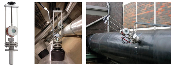
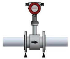
What are in-line and plug-in magnetic flowmeters?
Electromagnetic flowmeters are available as an integrated in-line version or as an insertion model. With special accessories (pull-out device) it is possible to install and remove them during operation without any problems, e.g. for maintenance purposes. For technical reasons, electromagnetic flowmeters are not available as clamp-on models.
How do you size a magnetic inductive flow meter?
Even if it is obvious to dimension the measuring device based on the pipe diameter, this is not the correct way if you want your measuring device to work properly. The essential criteria are a completely filled pipe system and a stable flow profile.
The best approach is to know the maximum and minimum flow ranges that will flow through the meter. Choose a meter that can capture and process flow for both maximum and minimum flow.
What do I have to consider when installing an electromagnetic flow meter?
• Make sure that the flow rate is within a range to ensure reliable measurement between the minimum and maximum flow rates.
• Make sure that the medium to be measured by the measuring device has the minimum conductivity required for your measuring device
• In-Line Piping Requirements: Ensure meter placement meets proper upstream and downstream piping requirements.
• Observe the specifications of your magnetic flow meter.
• For drop-in electromagnetic flowmeters, ensure that the upstream piping is adequate to help stabilize the flow profile. In exceptional cases, this can require a 20-fold inlet section or more.
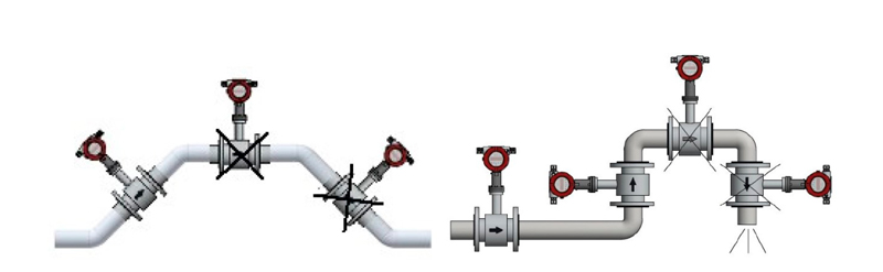
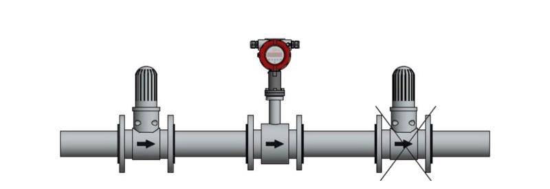
• Make sure the gauge is not installed close to other elements that will disturb the flow profile, such as e.g. B. Valves, pumps and bends in the pipe. Valves should generally be located downstream of the meter.
• When installing the meter, ensure that all fittings, gaskets, and other items are properly aligned to avoid unnecessary flow turbulence.
• If the installation requires multiple gauges to be installed close together on a single pipe, ensure there is adequate space between gauges.
• Ground the meters: Since the signal produced by the meter is very weak, make sure there is a complete ground connection.
• Ensure a completely filled tube: Since magnetic flow meters require a completely filled tube, there must be no bubbles or flow failures. To avoid these errors, it is preferable to always install the EMF with the flow upwards in vertical piping installations. Also note where the gauge generally relates to the height of the rest of the process. If installed at the highest point of the pipeline, gravity could cause flow reduction.
• Isolate the measuring devices: Make sure that the measuring device is not affected by nearby objects that contain magnets or generate magnetic fields, as this would seriously disturb the magnetic principle of operation.
Checklist and notes for the installation of magnetic inductive flow meters
| Device Size | Does the device size match the flow rate? |
| Media Conductivity | Is the required minimum conductivity maintained over the full operating temperature range of the flow meter? |
| Inline Version | Are the inlet and the outlet guaranteed? |
| Plug-in Version | Is the inlet section 20x DN inner diameter guaranteed? |
| Flow Profile | Could there be turbulence in the medium or is this impossible due to the design? |
| Process Connections | Do the process connections match the system and the measuring device? |
| Distance | Are the minimum distances guaranteed when using several measuring devices? |
| Grounding | Is earthing guaranteed? |
| Completely Filled Tube | Could there be gas or air bubbles in the medium or is this impossible due to the design? |
| Distance to Interfering Fields | Could neighboring electromagnetic fields influence the measurement or is this impossible due to the design? |
| Bypass Pipe Option | A bypass pipe can be installed for easy disassembly or cleaning of the sensor. This design is recommended for heavily contaminated media. |
| Lining of the Flow Body | If the flow body is lined with PTFE, the flow meter must be installed with special care. The hose lining is bordered at the flanges (seal). This must not be damaged or removed as it prevents the liquid from penetrating between the flange and the flow body and damaging the electrode insulation. |
| Flow Meter Connections | The sensor is installed between the pipes using suitable screws, bolts, nuts and gaskets. Do not exceed torque recommendations when installing. Make sure ground rings are properly connected. Any seals installed must not impede the pipe cross-section. Do not use conductive sealants such as graphite. This could lead to a conductive layer forming on the inside of the measuring tube, which interferes with the measuring signal. |
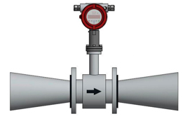
| Installation in a Pipeline with a Larger Diameter | The installation of the flowmeter in pipelines with larger nominal widths is possible by using pipe tapers, however, the resulting pressure loss must be taken into account. In order to avoid flow interruptions in the flow tube, a reduction angle of the tapers of 8° should not be exceeded. |
| Vibrations | To eliminate the effects of vibration and prevent premature damage to the transmitter, flanged flow meters require the sensor to be supported near the flanges. |
Magnetic inductive flow meter with a smaller inner diameter is installed in a pipe with a larger inner diameter using reducers.
In order to avoid damage to the device and the system, supports must be attached in the event of vibrations.
Always place the magnetic inductive flow meter in rising pipe sections.
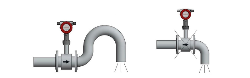
Free outlet of a magnetic inductive flow meter
The device should preferably be installed in a siphon. The empty pipe detection circuit in the converter offers additional security to detect empty or partially filled pipelines.
Danger! Risk of accumulation of solids in the siphon. The installation of a cleaning opening in the pipeline is recommended.
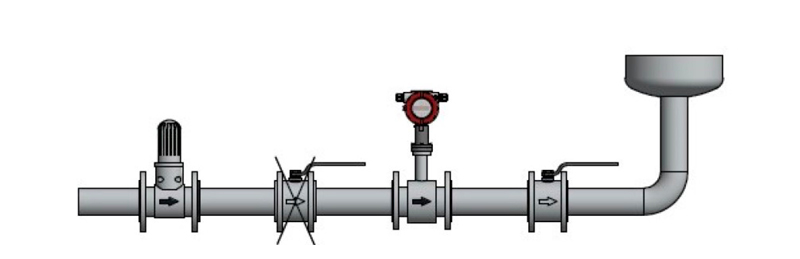
Long pipeline with the magnetic inductive flow meter
Since pressure surges are possible with long pipelines, control and shut-off devices must be installed behind the sensor. However, when installing in vertical pipelines, especially in the case of measuring tubes with PTFE lining and at higher operating temperatures, the control and shut-off devices should be installed in front of the sensor (risk of vacuum!).
Installation of pumps in the magnetic inductive flow meter
Sensors must not be installed on the intake side of pumps. This avoids the risk of negative pressure and thus possible damage to the measuring tube lining.
Grounding for magnetic inductive flowmeters: metal pipe electrically conductive
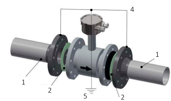
Legend: 1 Pipe 2 Gasket 3 - 4 Ground wire min. 4 mm^2 Cu 5 earth connection
Grounding for magnetic inductive flowmeters: Plastic piping or internally coated metal piping is not conductive
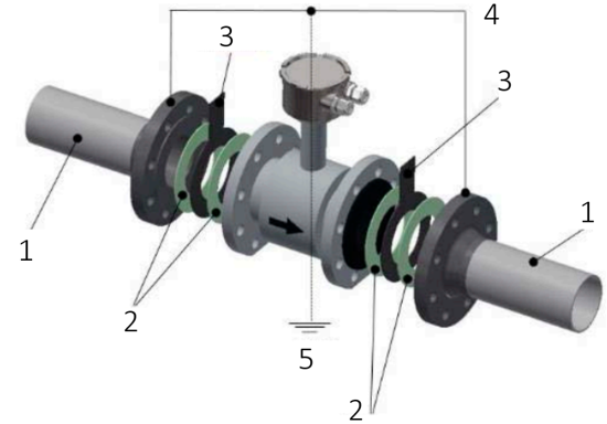
Legend: 1 Pipe 2 Gasket 3 Ground ring 4 Grounding wire min. 4 mm^2 Cu 5 Ground connection
What connections do electromagnetic flowmeters have?
The MIK has connections from G 1/2 to G2 3/4 AG, our popular product MIM connections from G 1/4 to G2 and NPT. For larger pipes, we recommend the MIS with DN50, DN80, DN100 and ANSI 2", 3", 4" connections. For even larger pipes such as DN 10 to DN 1200 or ANSI 1/2 to 48", use our EPS. And as a plug-in version, you can order our PIT for connections from DN150 to DN 2000. Custom-made products can be delivered quickly and conveniently on request.
For which pressures are magnetic inductive flow meters suitable?
The magnetically inductive flow meter (model designation at Kobold: EPS) requires media pressures between 0 and 40 bar. Higher pressures are possible on request.
How to choose a magnetic flow meter?
We will be happy to help and advise you on your selection! Visit our website www.kobold.com. Call us or send us an email.
Are magnetic flow meters ATEX approved for hazardous areas?
ATEX approval is selectable as an option. Call us or send us an email.
I need urgent technical help. How can I get in contact with you?
We're here to help! Call us or send us an email.
Other Members of the KOBOLD group
